.world file - M2TW
Contents
- 1 Overview
- 2 File Structure
- 2.1 Table 1 (bounding boxes and complex assignment)
- 2.2 Table 2 (object information)
- 2.3 Complex Information
- 2.4 Referenced Files
- 2.5 Pathfinding Tables
- 2.6 Game Objects Section
- 2.7 Perimeter
- 2.8 Defensive Points
- 2.9 Anim Strings Section
- 2.10 Structural Effects
- 2.11 Six Float Table
- 2.12 Bottom Table 1
- 2.13 Bottom Table 2
- 2.14 Bottom Table 3
- 2.15 Bottom Strings
- 3 Modding Information
Overview
The .world file forms the major part of the information controlling each settlement or ambient building in M2TW. The file contains details of the 3d structures making up each building, wall or other static object. It is very closely interrelated to the .worldcollision file.
The 3d game elements are grouped into:
- Complexes Each complex is numbered (0 to n)in Table 1 and can comprise one or more structures.
- Structures Each structure can comprise one or more objects, a structure can be viewed as a Milkshape ms3d file or in Mayavi2 by use of the WorldEditor user developed modding tool.
- Objects Each object can comprise one or more groups, where an object contains more than one group the first will be the undamaged state of the 3d element and the successive groups will be the damaged states. The most common object size is two groups - a pair of undamaged and damaged versions of an element.
- Groups In game groups are the same as Milkshape ms3d groups, they are organised into objects by the .world files.
Each of the above element stages will also have an invisible bounding sphere or box which effects where it can be viewed from in game (and probably other factors like collision and animation). The complex bounding spheres are located within an Octree structure of bounding boxes described by Argantonio here.
Co-ordinates in the world files generally appear in the order x,y,z. Relative to the game the x axis is east-west (using the convention that north is up), the y axis is the height, and the z axis is north-south.
File Structure
NOTE: The illustrations given, unless otherwise stated are from Stone_Fort_C from the Kingdoms Britannia mod. There are some differences between Kingdoms and earlier M2TW files, but the same general principles should apply. Illustrations are derived from the .textrep file produced by the WorldEditor with sections transferred into excel to allow highlighting. The unedited .world file does not look anything like that, and indeed is only remotely legible through use of the editor.
The file layout (with names used in KnightErrant's WorldEditor ) is as follows:
Table 1 (bounding boxes and complex assignment)
This table deals with the inter-relation of the bounding boxes and Complex relative locations and bounding spheres.
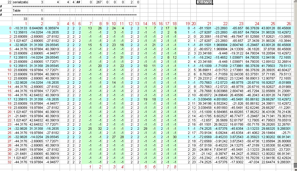
The image below shows a screen shot of Table 1 from Stone_Fort_C which has been coloured in Excel to try to attempt to explain contents.

Row Numbers
The numbers in red do not exist in the file - they are notional column and row numbers added to help explain things. The notional row numbers (0-32 in the example) although not stated in the file are actually used within the table to inter-relate components.
The row numbers also are used later in the complex section - the number at the end of the 'Argantonio integers' (the calculated maximum triangle count) for each complex is its table 1 row number.
Column 19
Column 19 gives the hierarchy level for each of the row contents.
- 0 is the top level cube for the Octree structure - the dimensions of this should contain the entire 3d world for this settlement or building.
- 1 is the second level down, the up to eight smaller cubes that can fit within the largest cube
- 2 is the third level down, theoretically up to 64 smaller cube locations that can fit within the level 1 cubes - in this file the 3d Complexes are notionally located in the level 2 cubes - they can exceed the size of the cube and overlap other cubes in some cases.
Column 20
Column 20 gives the Complex number (with the Complexes numbered 0-23 in this example, if column 20 has the entry "-1" the row doesn't reference a Complex but is instead a bounding box which contains other rows (a level 0 or 1 box as described above). These rows that only contain other rows have been marked in light blue on the diagram.
Columns 7 to 18
These columns represent the eight possible positions (the columns containing only "2" are spacers) within one bounding box cube for another smaller bounding box cube to exist in the Octree system. If the number in these columns (shown in light green on the diagram) is not "-1" then it represents the notional row number of the bounding cube or Complex that is located at that position.
You can see that the top level bounding box cube in row 0 contains all eight level 1 bounding box cubes at rows 13, 26, 24, 4, 1, 7, 17 and 9.
If you look at bounding box row 24, you will see it includes complex rows 25, 32 and 29 (so not just those displayed between it and the next level 1 row!). Viewing column 20 for those rows will show that the actual 3d Complexes contained in that level 1 bounding box are 17, 20 and 23 (with complex numbering starting at 0).
Complexes and smaller boxes are distributed into the eight possible grid positions in the larger boxes following a set pattern with the first position having the lowest x,y,z co-ordinate values and the 8th position the highest x,y,z co-ordinate values. (If you really need to understand where to place new components in the system you need to draw a 3d diagram of the relative positions)
Columns 1 to 3
The co-ordinates in these columns are the x,y,z co-ordinates for the centre of the Octree box each row relates to. The co-ordinates in row 0 represent the nominal centre for this entire world and its largest Octree box. The length of side for the largest box in this example is 90.6779251099 x 2 the number seen above the table, so the dimensions of the box will be + and - 90.6779251099 from the centre locations in row 0 columns 1 to 3.
Columns 21 to 26
The co-ordinates in these columns are the minimum x,y,z co-ordinates (in columns 21 to 23) and maximum x,y,z co-ordinates (in columns 24 to 26) that define the diagonally opposite corners of the effective bounding box applied to whatever is in that row (either smaller bounding boxes or Complexes). These bounding box dimensions can and do overlap each other and do not necessarily fill the entire Octree box size they fit within.
Table 2 (object information)
Table 2 contains the information for all the objects in the .world - they are listed in sequence.
For each object the following information is provided;
- Complex number
- Structure number
- No of groups
- A code for type description (e.g. gate or default)
- Sequence number (position in game objects list if a tower/gate etc)
- Attribute (identifies walls breachable or blocked, gates & tower upgrades)
- Perimeter assignment
- Pathfinding Sequence (references the breach path used if any)
- Animation reference (refers to the animation according to position in anims list if used)
- Effects reference (refers to the effect assigned see seven float table)
- Deployment area (each object can exist in up to three deployment blocks - this only actually occurs if chunks of wall stick out either side of a tower)
Complex Information
This is the model information for each structure in the complex. Structure information includes triangles/vertex positions/normals/shading info/effect illumination info and uv mapping information - the model information ends with a bounding sphere for the structure.
The complex info ends with texture information for each structure and a bounding sphere for the complex and a reference to the effects that are to be applied to objects within the complex (max number of effects = 69)
Referenced Files
the .worldterrain, .worldpathfinding and .worldvegetation files to be used with the .world are listed here, e.g.
85 settlements/North_European/ambient_settlements/Stone_Fort_C/Stone_Fort_C.worldTerrain
89 settlements/North_European/ambient_settlements/Stone_Fort_C/Stone_Fort_C.worldPathfinding
88 settlements/North_European/ambient_settlements/Stone_Fort_C/Stone_Fort_C.worldVegetation
the length of the path is encoded before the file name.
Pathfinding Tables
This section deals with deployment blocks (how units are allowed to stand on walls), the doors and links that allow them to get onto walls, and breaches (for gates and walls) and bridges, and the 'doors' that access those breaches/bridges.
Table Blocks
These are the deployment blocks. The start of each block gives its block number (they're in sequence after the link/ladders) and the door numbers that are attached to the block.
Then follows co-ordinates defining the 'standable' area for each group of each object - walls which have progressively less standable area as they are damaged/destroyed will have reduced and more complex areas for the subsequent damaged groups.
Then follows a list of the coordinates for spots the troops can stand/be deployed on, this controls the unit spacing when stationary. The locations are all related to the undamaged state of walls - if the wall is damaged troops still standing on the now un-usable spots will be killed.
Links and ladder paths (wacky data)
(KE named this section 'wacky entries' etc at the stage when no-one had worked out what they were...)
This section contains the information for the links between 'doors'.
The first line gives the reference number for the link/ladder entry and then the reference number of the start and finish door. At least one door must be assigned to a deployment block, the other can be on an adjacent block or at ground level. The data gives the co-ordinates of the start/finish doors and the co-ordinates of any change point on the path - it also includes the distance between the points - having the correct distance there makes the troops appear to travel at the 'correct' speed.
Vanilla settlements have the link/ladder paths hidden in towers etc. This is advisable because units do not behave properly on the ladders, i.e. they do not respect each others collision areas and can visually merge together / pass through each other!
Doors and access points (7 float data)
This is the information for the 'doors'. There are two doors for each link/ladder and for each breach (wall or gate) & bridge. Each entry gives the door reference number, its co-ordinates, direction of travel, and lists the links/deployment blocks or pathfinding table (for bridge/breach) that its attached to. The final entry is a type code showing if it's a link attached door (single door), gate access or breach/bridge access.
Gates, breaches and bridges (Pathfinding Data)
This section gives details of the breaches and bridges, these over-rule the .worldpathfinding data when active.
Bridges will be active all the time. Wall breaches will only be active when the wall is destroyed. Gate breaches will be active when the gate is destroyed or the owner of the gate attempts to use it.
The data includes the co-ordinate of the center of the breach/bridge - its number of rows and columns (uses the same 2m grid as .worldpathfinding) - its height - and an entry for each point on the grid which specifies if its blocked or not.
Game Objects Section
For a settlement this will start with information including the Plaza location and the deployment outline (which controls the extent of the defenders deployment during battle set-up). Reflective planes will also have an entry here if they exist. After the main objects are listed there is a list of all the types of game objects that are used in the .world e.g.
7  Default
9  GateHouse
4  Gate
4  Wall
10  ArrowTower
The order of this list depends on which type of main object is assigned to the first applicable object. The list order is used in table 2 to identify which object uses wall/gate etc.
Main Objects Section
This starts with a list of the objects that are not 'game objects' e.g. towers/gates/gatehouses/walls.
ArrowTower Sections
Each arrow tower seems to relate to one object position. Where multiple objects are listed eg:
10 ArrowTower
 3
 1 156
 1 157
 1 158
 4   4
13
the objects in red are in the same location as the first object 156 but are the tower upgrade versions - eg the versions that only appear when the arrow firing is upgraded to canon firing etc.
FlagBase
Always follows the ArrowTower section - is the co-ordinate position for the flag that appears when the tower is activated by having allied troops nearby.
ArrowSlot Sections
The functioning of an arrow slot - the animation of firing projectiles etc. is coded elsewhere in the files / exe - think of this as the 'standard' arrow slot.
The ArrowSlot listing in the game object section shows where an individual arrow slot is placed, and how it's orientation is rotated as compared to the standard arrow slot.
4  0    3126
9 ArrowSlot
  3
10 GameObject
1 1
14 GameObjectName
9 ArrowSlot
14 GameObjectType
5 point
 +1.0000000   +0.0000000   +0.0000000  -15.9577274
 +0.0000000   +1.0000000   +0.0000000  +15.0830030
 +0.0000000   +0.0000000   +1.0000000  -26.1242752
 +0.0000000   +0.0000000   +0.0000000   +1.0000000
The numbers in red are the x, y, z, co-ordinates of the slot in that order. The block of 3 x 3 numbers before them dictate the relative orientation of the slot (as compared to the standard arrow slot). This example is with the slot in the same orientation as the standard arrow slot.
This block of 3 x 3 numbers is a rotation matrix, see here for an explanation of that related to an aeroplane's heading, attitude and banking. As none of the towers in the game lean away from vertical or horizontal the slots only revolve around the y axis; so in our case 'attitude' and 'banking' are always zero. So the equation on that explanation page of:
| ch*ca | -ch*sa*cb + sh*sb | ch*sa*sb + sh*cb |
| sa | ca*cb | -ca*sb |
| -sh*ca | sh*sa*cb + ch*sb | - sh*sa*sb + ch*cb |
can be simplified, as cos'attitude' and cos'bank' are always 1 and sin'attitude' and sin'bank' are always 0, substituting those values for ca cb sa and sb gives
| cos'heading' | 0 | sin'heading' |
| 0 | 1 | 0 |
| -sin'heading' | 0 | cos'heading' |
where heading is the angle of rotation from the standard orientation of a slot (which seems to be one based at origin and pointing towards the 6 oClock position down the z axis)
Gatehouse Sections
Gatehouses will have flag/arrow slot setting sections similar to the above - they may additionally have Oil Slots.
Wall Sections
Wall objects will have docking points for ladders/towers/rams as applicable listed.
Gate Sections
Gate objects will have docking points for rams listed.
Perimeter
Here the number of perimeters - and which objects are assigned to them are listed.
Defensive Points
If used the co-ordinates of defensive points (the fall back positions when the walls are breached) are given here.
Anim Strings Section
This contains a list of all the animations used - they're included as sets - typically a wall will have 3-5 transitions and a gate will have 8. The simplest entries will be for towers which only have 1 transition, e.g.
  1        Number of pairs of transitions....
#----
17 DamageTransition0
146 BlockSet/North_European/Animations/Tower_Castle_Animations/Castle_Large_Stone_Tower_Animations/large_castle_square_8m_arrow_tower_animation_a.anim
The sequence of this list is used in table 2 to assign the animation to the object.
Structural Effects
This section gives data for all the 'effects' applied to objects in the .world. Effects typically include lights, camp fires, dust/fire when damaged, fountains & sounds.
Structural Effects ( Variable Integers Table )
This gives entries for each effect/set of effects used by a collision. The effect used is determined by a reference to its list in the bottom strings section. The table then includes data for the position of the effect relative to the collision and a list of each object using the collision and a paired reference to the line that object uses in the six float table below.
Structural Effects ( Six Float Table )
For each effect and each object combination there is a line in this table which lists the co-ordinate for the effect (derived from the relative position to the collision and the object's collision entry).
Six Float Table
Bottom Table 1
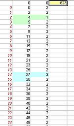
 This table effectively gives the object numbering system. The number at the top is the total number of Objects (sets of groups) in this .world file. There are then that number of rows in the following table section, if we use notional row numbers again (not in the file but added to the screen shot in red), we can find the object number of any group set.
The number in column 1 (text in black) is the group number for the first group in the first object, starting with the first group as 0; the number in the second column is the number of groups included in that object. As the first object contains 2 groups (which will be a paired set of undamaged and damaged versions of the element) then groups 0 and 1 must be included in that object. So it starts again on the next row with group 2 as start of next object, which again includes 2 groups so next start is 4, this only includes one group so group5 is start of next object, etc, etc....
Note: the group numbering is based on the occasionally scrambled (bits of structure 2 numbered before all of structure 1) system in Bottom Table 3
Bottom Table 2
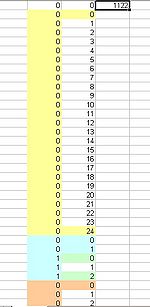
Nice and simple this one: The total number of groups (1122 for Stone_Fort_C) at the top then that number of rows below. With the number of the group (0-1121 for the example) in sequence down the first column then a 1 on each row.
Looks like a very long way of saying there's 'x' number of groups?
Bottom Table 3
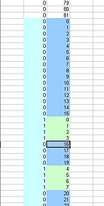
In the view on the left you can see the start of bottom table 3 from Stone_Fort_C - the 1122 number at the top is the total number of groups in this settlement (this is Milkshape type groups, so there are more of these than the objects which can be made up of sets of groups).
The number in the first column represents the structure number within a complex, 0 is the first structure in a complex. The numbering in the second column is the group number - so you can see that the first structure shown has 25 groups (0-24). When the numbering in the second column restarts from 0 again that is the start of a new structure - the number in the first column at that point is still 0, so this is still the first structure in a complex = therefore this is a new complex. When the numbering in column 2 again starts from 0 the number in column 1 changes to 1 representing the second structure in a complex.
From all that you get Complex 1 has 1 Structure with 25 Groups, Complex 2 has 2 Structures, the first with 2 Groups the second with 3 Groups. (luckily that ties up with what is visible when you open those Complex Structures in Milkshape through the editor)
So far so good - you can see that the start of a new complex is signalled when the number in both columns on the same row is 0 - i.e. its the first group in the first structure, so it must be the start of a complex.
The picture on the right shows a point where it gets a bit more confusing. It's switched to the second structure, but then goes back to the first structure (it's obviously not a new structure or complex as it's not starting at the first group) there is a chunk of the first structure within the sequence for the second structure and then it returns to first structure again.....
Why does this all matter you may ask! Well the sequence of this list gives you the numbering system for the objects (once you've excluded the groups which are the second part of pairs etc). The object numbering appears in a variety of places elsewhere in this file and the collision file, you must know your objects number to give it the right collision item or structural effect.... though quite why the existing objects don't just work in structure order is a mystery!

