.worldcollision file - M2TW
Contents
Overview
The .worldcollision file contains the information that makes objects appear solid in the game, e.g. so siege weapon fire hits the structure instead of passing straight through. It does not effect units being able to walk through buildings, as units can sometimes enter buildings, whether they are able to or not is defined in the .worldpathfinding file.
Each settlement or ambient building must have a .worldcollision file with the same name and inside the same folder as its .world file (the path to the .worldcollision file is not specified in any modifiable file so this can not be changed)
Diagrams and examples shown in this page are from the North European ambient Stone_Fort_C unless otherwise stated.
File Structure
The file layout (with names used in KnightErrant's WCEditor is as follows:
Table 1
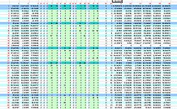
This table deals with the inter-relation of the bounding boxes and collision objects, their relative locations and bounding spheres. It is very similar in layout and effect to the . world file Table 1
The numbers in red do not exist in the file - they are notional column and row numbers added to help explain things. The notional row numbers although not stated in the file are actually used within the table to inter-relate components.
Column 19
Column 19 gives the hierarchy level for each of the row contents, in the collision file there is one more hierarchy level than in the .world file.
- 0 is the top level cube for the Octree structure
- 1 is the second level down, up to eight smaller cubes that can fit within the largest cube can exist at this level(rows marked mid blue in diagram), in the collision file this is split into a further subdivision
- 2 is the third level down in the collision file this still contains only other smaller bounding boxes(rows marked light blue in diagram)
- 3 this level contains the actual objects.
Column 20
Column 20 gives the row number in table 2 that contains the actual objects, if column 20 has the entry "-1" the row doesn't reference objects in table 2 but is instead a bounding box which contains other rows (a level 0, 1 or 2 box as described above).
Columns 7 to 18
The columns shown in light green represent the eight possible positions within one bounding box cube for another smaller bounding box cube to exist in the Octree system. If the number in these columns is not "-1" then it represents the notional row number for the lower hierarchy row within this table that is included at that relative position within this row's larger box.
For example in the annotated screen shot above row number 7 which is a level 1 box shows that it contains within it the level 2 boxes in rows 12, 24, 12 and 8. The level 2 box at row 8 shows that it contains within it the contents of rows 9 and 58. Row 9 is a lowest level box - so its contents at column 20, in this case the number "3", means it includes the contents of Table 2 row 3 (actually the 4th row as row numbering starts at 0).
Columns 1 to 3
The co-ordinates in these columns are the x,y,z co-ordinates for the centre of the Octree box each row relates to. The co-ordinates in row 0 represent the nominal centre for this entire world and its largest Octree box.
Columns 21 to 26
The co-ordinates in these columns are the minimum x,y,z co-ordinates (in columns 21 to 23) and maximum x,y,z co-ordinates (in columns 24 to 26) that define the diagonally opposite corners of the effective bounding box applied to whatever is contained in that row (either smaller bounding boxes or object groups from Table 2). These bounding box dimensions can and do overlap each other and do not necessarily fill the entire Octree box size they fit within.
Table 2
Table 2 indicates which Objects are included within the bounding boxes specified already by the rows in Table 1. The Objects being the combinations of 3d structural groups as already defined and numbered in the .world file.
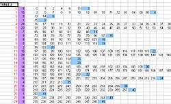
The annotated screen shot shows notional row numbers added to the table (marked in red) these row numbers are referenced in column 20 of table 1. The first column that actually appears in Table 2 (marked with mauve background in diagram) is a count of the number of Objects included in the following list. (Adding together this count for each of the rows will result in the total number of Objects in this world - as already defined in the .world file)
Then follows the list of object numbers included in each row - and hence in the relevant bounding box from Table 1.
The last figure on each line, is the notional row number from Table 1 that this collection of objects fits within. So (using the notional row numbers added in red) in the example diagrams shown; row 14 column 20 of Table 1 refers to row 6 in this table, and the last entry in row 6 of this table refers back to row 14 of Table 1.... tada!

