Difference between revisions of ".worldcollision file - M2TW"
(m2 logo) |
|||
| (25 intermediate revisions by 2 users not shown) | |||
| Line 1: | Line 1: | ||
| + | {{M2TW Modding Logo}} | ||
==Overview== | ==Overview== | ||
| − | |||
| − | Each settlement or ambient building must have a .worldcollision file with the same name and inside the same folder as its .world file (the path to the .worldcollision file is not specified in any modifiable file so this can not be changed) | + | |
| + | '''The .worldcollision file contains the information that makes objects appear solid in the game, e.g. so siege weapon fire hits the structure instead of passing straight through. It does not effect units being able to walk through buildings, as units can sometimes enter buildings, whether they are able to or not is defined in the [[.worldpathfinding]] file. | ||
| + | |||
| + | |||
| + | Each settlement or ambient building must have a .worldcollision file with the same name and inside the same folder as its [[.world]] file (the path to the .worldcollision file is not specified in any modifiable file so this can not be changed).''' | ||
Diagrams and examples shown in this page are from the North European ambient Stone_Fort_C unless otherwise stated. | Diagrams and examples shown in this page are from the North European ambient Stone_Fort_C unless otherwise stated. | ||
| + | |||
| + | This article refers to ''collision items'' - this is an invented name used in an attempt to avoid calling them objects and getting confused with the visible 3d objects which are defined and numbered in the .world file. (For anyone from RTW modding the collision item fulfils a similar function to the .info cas's which were combined into RTW buildings when .item files where created.) | ||
| + | |||
| + | A ''collision item'' can have just one component or have an undamaged version and extra components representing subsequent damage states. This should correspond to the same sequence as the objects which use that collision item - so a wall breach object that has 6 groups representing subsequent damage states should use a collision item that also contains 6 corresponding damage state groups. Each group in a collision item is represented by its own vertex table and can be extracted as an ms3d structure. | ||
| + | |||
| + | |||
| + | '''The [[IWTE]] tool allows collision items to be made or re-assigned without any further technical knowledge, the information below about file structure is retained for reference purposes only, it is not required for normal modding purposes.''' | ||
| + | |||
| + | To show how the .worldcollision affects things in-game in the example below normally visible structural groups have been moved backwards by changing the structure in the [[.world]] file, the pathfinding and docking information has been left as it was, and the collision volume has been moved forward and right: | ||
| + | |||
| + | [[Image:Objectmoved.jpg|frame|The unit that deployed the ladders to the old docking position then abandoned them - they wouldn't climb ladders because the deployment area where they would normally stand on top of the wall no-longer has a collision volume associated with it.]] | ||
| + | [[Image:Collisionmoved.jpg|frame|center|When the wall gets to the damage level where the animated transition comes in the wall appears in the collision volume location.]] | ||
==File Structure== | ==File Structure== | ||
| − | The file layout (with names used in [[KnightErrant]]'s WCEditor is as follows: | + | The file layout (with names as used in [[KnightErrant]]'s [[World_File_Editing_Tools_-_M2TW#.WorldCollision_File|WCEditor]] and [[IWTE]]'s text conversion), is as follows: |
| + | |||
| + | ---- | ||
| + | |||
===Table 1=== | ===Table 1=== | ||
| − | This table deals with the inter-relation of the bounding boxes and collision | + | This table deals with the inter-relation of the bounding boxes and collision items, their relative locations and bounding spheres. It is very similar in layout and effect to the [[.world_file_-_M2TW#Table_1|. world file Table 1]], see that article for more information and links re the Octree structure. |
[[Image:Collision-table1.jpg|thumb|250px]] | [[Image:Collision-table1.jpg|thumb|250px]] | ||
| Line 17: | Line 36: | ||
====Column 19==== | ====Column 19==== | ||
Column 19 gives the hierarchy level for each of the row contents, in the collision file there is one more hierarchy level than in the .world file. | Column 19 gives the hierarchy level for each of the row contents, in the collision file there is one more hierarchy level than in the .world file. | ||
| − | :0 is the top level cube for the [ | + | :0 is the top level cube for the [https://www.twcenter.net/forums/showthread.php?p=4273886&highlight=octree#post4273886 Octree] structure |
:1 is the second level down, up to eight smaller cubes that can fit within the largest cube can exist at this level(rows marked mid blue in diagram), in the collision file this is split into a further subdivision | :1 is the second level down, up to eight smaller cubes that can fit within the largest cube can exist at this level(rows marked mid blue in diagram), in the collision file this is split into a further subdivision | ||
:2 is the third level down in the collision file this still contains only other smaller bounding boxes(rows marked light blue in diagram) | :2 is the third level down in the collision file this still contains only other smaller bounding boxes(rows marked light blue in diagram) | ||
| − | :3 this level contains the actual objects. | + | :3 this level contains the actual objects (via the row grouping in Table 2). |
====Column 20==== | ====Column 20==== | ||
| Line 38: | Line 57: | ||
| + | ---- | ||
===Table 2=== | ===Table 2=== | ||
| − | Table 2 indicates which | + | Table 2 indicates which objects are included within the bounding boxes specified already by the rows in Table 1. The objects being the combinations of 3d groups as already defined and numbered in the .world file. All objects are included in this table even if they don't use a collision item. |
[[Image:Collision-table2.jpg|thumb|250px]] | [[Image:Collision-table2.jpg|thumb|250px]] | ||
| − | The annotated screen shot shows notional row numbers added to the table (marked in red) these row numbers are referenced in [[.worldcollision_file_-_M2TW#Column_20|column 20 of table 1]]. The first column that actually appears in Table 2 (marked with mauve background in diagram) is a count of the number of Objects included in the | + | The annotated screen shot shows notional row numbers added to the table (marked in red) these row numbers are referenced in [[.worldcollision_file_-_M2TW#Column_20|column 20 of table 1]]. |
| + | |||
| + | The first column that actually appears in Table 2 (marked with mauve background in diagram) is a count of the number of Objects included in the list that follows on that row. (Adding together this count for each of the rows will result in the total number of Objects in this world - as already defined in the .world file) | ||
| + | |||
| + | Then follows the list of Object numbers included in each row - and hence in the relevant bounding box from Table 1. | ||
| + | |||
| + | The last figure on each line, is the notional row number from Table 1 that this collection of objects fits within. So (using the notional row numbers added in red) in the example diagrams shown; row 14 column 20 of Table 1 refers to row 6 in this table, and the last entry in row 6 of this table refers back to row 14 of Table 1.... | ||
| + | |||
| + | Row 8 of the table in the example file contains objects, 89-94 and 622-623, these objects can be seen in table 3 to not have a collision item assigned, row 8 in this table cross references to row 16 in table 1, which is the row with null values for its bounding box. | ||
| + | |||
| + | |||
| + | ---- | ||
| + | |||
| + | ===Table 3=== | ||
| + | Table 3 consists of sequential blocks of co-ordinates and information for each of the objects in the game. (remember the numbered 'objects' are groups or combinations of groups already defined in the .world file) | ||
| + | |||
| + | [[Image:Collision-table3.jpg|thumb|250px]] | ||
| + | |||
| + | The example shown in this image shows the layout of the block for object number 458 (this object is the balcony in the example file Stone_Fort_C). The object number is in the second column (marked green in diagram). | ||
| + | |||
| + | The number in the first column defines the collision item that is used for this visible 3d object. The same collision item is frequently re-used for different visible 3d objects. Some collision items are as simple as a square plane, others represent a larger structural element such as a gatehouse or piece of wall. If an object does not use a collision item - which is unusual but applies to some small elements like torches "-1" is used in column 1, but the 3d object still has its co-ordinates recorded in the rest of the block as for the other objects. | ||
| + | |||
| + | The next 2 blocks of 4 x 4 co-ordinates controls the placing of the collision item. The co-ordinates marked in yellow are the centre points of the visible 3d object's placing in the world, x at the top, y in 2nd row, z in third row. These numbers are re-used in the last column with their sign (and sometimes location) varied to control the rotation of the collision item. (eg where the same collision item for a section of wall is used for different visible 3d objects forming parts of walls in different places on the map, it may be turned through 180 or 90 degrees etc..). ''the rotation needs more explanation - author can follow pattern but not work out logic...'' | ||
| + | |||
| + | The four co-ordinates at the end of each block (marked blue in the above diagram) are the co-ordinates for the bounding sphere for the object as, x,y,z and radius. | ||
| + | |||
| + | [[Image:Balcony-collision.jpg|thumb|250px]] | ||
| + | To look up the collision item for our Stone_Fort_C, object 458 (balcony) we need to find what Table 3 is calling Table 10 in the Central Table sections of the file. As .world file numbering starts at 0 this will be the eleventh table with a header section in the Central Table sections. In the [[WCEditor]] this comes up labelled Central Table 21 at the moment, here's a view of the collision item's first and only component in Mayavi2: | ||
| + | |||
| + | ---- | ||
| + | |||
| + | ===Central Tables=== | ||
| + | There is one Central Table with Header section for each of the collision items represented by a number used in column 1 of Table 3 (0 to 67 in the Stone_Fort_C example). Note that many of those numbers / collision items are re-used for multiple visible 3d objects with just the location and orientation changed via table 3. Therefore there are a lot less collision items than visible 3d objects in a typical settlement. (Stone_Fort_C has 627 visible 3d objects defined in .world, and only 68 collision items) | ||
| + | |||
| + | Much like the pairing effect seen in the world file, where a typical object consists of one undamaged and one damaged 3d group. The corresponding collision items also have undamaged and damaged versions. Where a collision item has one or more damaged versions they have additional table sections giving vertex model tables for their damaged states. | ||
| + | |||
| + | The header section that starts each collision item's set of tables, contains 4 co-ordinates, the 4th is the bounding sphere diameter. (This can be identified as the same as the 4th co-ordinate at the end of each corresponding Table 3 block) ''author not sure on first three co-ordinates - might be variation from geometric centre to centre of bounding sphere?'' | ||
| + | |||
| + | The Large Tables within each central table section contains the vertex co-ordinates of the 3d shape. | ||
| + | |||
| + | ---- | ||
| − | + | ===Last Table=== | |
| + | The last table has the same number of rows as there are objects as defined by the .world file (so 627 for our Stone_Fort_C example). The rows aren't numbered in the hex file but can be presumed to follow the objects in sequential number order. | ||
| − | + | Each row has 4 co-ordinates, these represent the x,y,z, and radius of the bounding sphere for each each object's collision item. | |
| + | These can, by inspection, be seen to be the same as the 4 co-ordinates at the end of that Object's Table 3 block entry. The exception to this being the 3d Objects which do not actually use a collision object (those with rows starting "-1" in Table 3), these have 0.0000 entries for the 4 co-ordinates. | ||
| + | ==External Links== | ||
| + | *''[https://www.twcenter.net/forums/showthread.php?323503-IWTE-World-editing-(General-Discussion) IWTE tool] | ||
| + | *''Early tutorial thread with some research information [https://www.twcenter.net/forums/showthread.php?t=310750 here].'' | ||
| − | [[Category: | + | [[Category:M2TW Battle Map Modding]] |
Latest revision as of 08:59, 1 July 2020
Contents
Overview
The .worldcollision file contains the information that makes objects appear solid in the game, e.g. so siege weapon fire hits the structure instead of passing straight through. It does not effect units being able to walk through buildings, as units can sometimes enter buildings, whether they are able to or not is defined in the .worldpathfinding file.
Each settlement or ambient building must have a .worldcollision file with the same name and inside the same folder as its .world file (the path to the .worldcollision file is not specified in any modifiable file so this can not be changed).
Diagrams and examples shown in this page are from the North European ambient Stone_Fort_C unless otherwise stated.
This article refers to collision items - this is an invented name used in an attempt to avoid calling them objects and getting confused with the visible 3d objects which are defined and numbered in the .world file. (For anyone from RTW modding the collision item fulfils a similar function to the .info cas's which were combined into RTW buildings when .item files where created.)
A collision item can have just one component or have an undamaged version and extra components representing subsequent damage states. This should correspond to the same sequence as the objects which use that collision item - so a wall breach object that has 6 groups representing subsequent damage states should use a collision item that also contains 6 corresponding damage state groups. Each group in a collision item is represented by its own vertex table and can be extracted as an ms3d structure.
The IWTE tool allows collision items to be made or re-assigned without any further technical knowledge, the information below about file structure is retained for reference purposes only, it is not required for normal modding purposes.
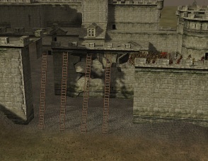
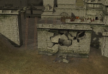
To show how the .worldcollision affects things in-game in the example below normally visible structural groups have been moved backwards by changing the structure in the .world file, the pathfinding and docking information has been left as it was, and the collision volume has been moved forward and right:
File Structure
The file layout (with names as used in KnightErrant's WCEditor and IWTE's text conversion), is as follows:
Table 1
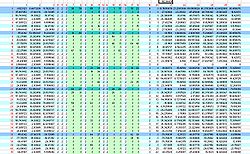
This table deals with the inter-relation of the bounding boxes and collision items, their relative locations and bounding spheres. It is very similar in layout and effect to the . world file Table 1, see that article for more information and links re the Octree structure.
The numbers in red do not exist in the file - they are notional column and row numbers added to help explain things. The notional row numbers although not stated in the file are actually used within the table to inter-relate components.
Column 19
Column 19 gives the hierarchy level for each of the row contents, in the collision file there is one more hierarchy level than in the .world file.
- 0 is the top level cube for the Octree structure
- 1 is the second level down, up to eight smaller cubes that can fit within the largest cube can exist at this level(rows marked mid blue in diagram), in the collision file this is split into a further subdivision
- 2 is the third level down in the collision file this still contains only other smaller bounding boxes(rows marked light blue in diagram)
- 3 this level contains the actual objects (via the row grouping in Table 2).
Column 20
Column 20 gives the row number in table 2 that contains the actual objects, if column 20 has the entry "-1" the row doesn't reference objects in table 2 but is instead a bounding box which contains other rows (a level 0, 1 or 2 box as described above).
Columns 7 to 18
The columns shown in light green represent the eight possible positions within one bounding box cube for another smaller bounding box cube to exist in the Octree system. If the number in these columns is not "-1" then it represents the notional row number for the lower hierarchy row within this table that is included at that relative position within this row's larger box.
For example in the annotated screen shot above row number 7 which is a level 1 box shows that it contains within it the level 2 boxes in rows 12, 24, 12 and 8. The level 2 box at row 8 shows that it contains within it the contents of rows 9 and 58. Row 9 is a lowest level box - so its contents at column 20, in this case the number "3", means it includes the contents of Table 2 row 3 (actually the 4th row as row numbering starts at 0).
Columns 1 to 3
The co-ordinates in these columns are the x,y,z co-ordinates for the centre of the Octree box each row relates to. The co-ordinates in row 0 represent the nominal centre for this entire world and its largest Octree box.
Columns 21 to 26
The co-ordinates in these columns are the minimum x,y,z co-ordinates (in columns 21 to 23) and maximum x,y,z co-ordinates (in columns 24 to 26) that define the diagonally opposite corners of the effective bounding box applied to whatever is contained in that row (either smaller bounding boxes or object groups from Table 2). These bounding box dimensions can and do overlap each other and do not necessarily fill the entire Octree box size they fit within.
Table 2
Table 2 indicates which objects are included within the bounding boxes specified already by the rows in Table 1. The objects being the combinations of 3d groups as already defined and numbered in the .world file. All objects are included in this table even if they don't use a collision item.
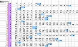
The annotated screen shot shows notional row numbers added to the table (marked in red) these row numbers are referenced in column 20 of table 1.
The first column that actually appears in Table 2 (marked with mauve background in diagram) is a count of the number of Objects included in the list that follows on that row. (Adding together this count for each of the rows will result in the total number of Objects in this world - as already defined in the .world file)
Then follows the list of Object numbers included in each row - and hence in the relevant bounding box from Table 1.
The last figure on each line, is the notional row number from Table 1 that this collection of objects fits within. So (using the notional row numbers added in red) in the example diagrams shown; row 14 column 20 of Table 1 refers to row 6 in this table, and the last entry in row 6 of this table refers back to row 14 of Table 1....
Row 8 of the table in the example file contains objects, 89-94 and 622-623, these objects can be seen in table 3 to not have a collision item assigned, row 8 in this table cross references to row 16 in table 1, which is the row with null values for its bounding box.
Table 3
Table 3 consists of sequential blocks of co-ordinates and information for each of the objects in the game. (remember the numbered 'objects' are groups or combinations of groups already defined in the .world file)
The example shown in this image shows the layout of the block for object number 458 (this object is the balcony in the example file Stone_Fort_C). The object number is in the second column (marked green in diagram).
The number in the first column defines the collision item that is used for this visible 3d object. The same collision item is frequently re-used for different visible 3d objects. Some collision items are as simple as a square plane, others represent a larger structural element such as a gatehouse or piece of wall. If an object does not use a collision item - which is unusual but applies to some small elements like torches "-1" is used in column 1, but the 3d object still has its co-ordinates recorded in the rest of the block as for the other objects.
The next 2 blocks of 4 x 4 co-ordinates controls the placing of the collision item. The co-ordinates marked in yellow are the centre points of the visible 3d object's placing in the world, x at the top, y in 2nd row, z in third row. These numbers are re-used in the last column with their sign (and sometimes location) varied to control the rotation of the collision item. (eg where the same collision item for a section of wall is used for different visible 3d objects forming parts of walls in different places on the map, it may be turned through 180 or 90 degrees etc..). the rotation needs more explanation - author can follow pattern but not work out logic...
The four co-ordinates at the end of each block (marked blue in the above diagram) are the co-ordinates for the bounding sphere for the object as, x,y,z and radius.
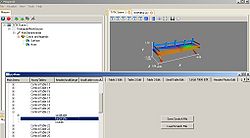
To look up the collision item for our Stone_Fort_C, object 458 (balcony) we need to find what Table 3 is calling Table 10 in the Central Table sections of the file. As .world file numbering starts at 0 this will be the eleventh table with a header section in the Central Table sections. In the WCEditor this comes up labelled Central Table 21 at the moment, here's a view of the collision item's first and only component in Mayavi2:
Central Tables
There is one Central Table with Header section for each of the collision items represented by a number used in column 1 of Table 3 (0 to 67 in the Stone_Fort_C example). Note that many of those numbers / collision items are re-used for multiple visible 3d objects with just the location and orientation changed via table 3. Therefore there are a lot less collision items than visible 3d objects in a typical settlement. (Stone_Fort_C has 627 visible 3d objects defined in .world, and only 68 collision items)
Much like the pairing effect seen in the world file, where a typical object consists of one undamaged and one damaged 3d group. The corresponding collision items also have undamaged and damaged versions. Where a collision item has one or more damaged versions they have additional table sections giving vertex model tables for their damaged states.
The header section that starts each collision item's set of tables, contains 4 co-ordinates, the 4th is the bounding sphere diameter. (This can be identified as the same as the 4th co-ordinate at the end of each corresponding Table 3 block) author not sure on first three co-ordinates - might be variation from geometric centre to centre of bounding sphere?
The Large Tables within each central table section contains the vertex co-ordinates of the 3d shape.
Last Table
The last table has the same number of rows as there are objects as defined by the .world file (so 627 for our Stone_Fort_C example). The rows aren't numbered in the hex file but can be presumed to follow the objects in sequential number order.
Each row has 4 co-ordinates, these represent the x,y,z, and radius of the bounding sphere for each each object's collision item.
These can, by inspection, be seen to be the same as the 4 co-ordinates at the end of that Object's Table 3 block entry. The exception to this being the 3d Objects which do not actually use a collision object (those with rows starting "-1" in Table 3), these have 0.0000 entries for the 4 co-ordinates.

