Difference between revisions of "Blender hints and tips"
(templates) |
(→Bone Assignment: added sections) |
||
| (4 intermediate revisions by the same user not shown) | |||
| Line 1: | Line 1: | ||
{{RTW M2TW Modding Logo}} | {{RTW M2TW Modding Logo}} | ||
{{IWTE}} | {{IWTE}} | ||
| + | '''Rome Remastered .cas assets can be converted to .dae (Collada interface) using IWTE, or to .fbx using Ferals' [https://github.com/FeralInteractive/romeremastered/tree/main/tools/CasPacker CasConv tool]. | ||
| + | |||
'''For information specific to using [[Blender]] in conjunction with IWTE for M2TW Battlemap Buildings please see [[IWTE - Settlements in Blender]]. For information on working on RTW and M2TW Units or Characters in Blender see [[IWTE - Units in Blender]].''' | '''For information specific to using [[Blender]] in conjunction with IWTE for M2TW Battlemap Buildings please see [[IWTE - Settlements in Blender]]. For information on working on RTW and M2TW Units or Characters in Blender see [[IWTE - Units in Blender]].''' | ||
This page consists of more general tips which may be suited to use of Blender for other aspects of Total War Modding. Information given is for Blender 2.8 unless otherwise noted. | This page consists of more general tips which may be suited to use of Blender for other aspects of Total War Modding. Information given is for Blender 2.8 unless otherwise noted. | ||
| + | |||
==Textures== | ==Textures== | ||
| Line 10: | Line 13: | ||
[[File:Texture-in-blender.jpg|How to open an image texture in Blender]] | [[File:Texture-in-blender.jpg|How to open an image texture in Blender]] | ||
| + | For dae to cas conversion IWTE uses the material name for the texture name to be encoded into the .cas file. The example in the picture 'unit_greek_royal_cavalry_macedon_tga' will be encoded as "textures/unit_greek_royal_cavalry_macedon.tga" | ||
| + | |||
| + | If you need ## prefix to a texture use hh_ and if you need #& prefix use ha_ | ||
| + | |||
| + | These translations in the texture name are used to avoid problems in the dae process caused by . # & symbols. | ||
==Animated Models== | ==Animated Models== | ||
| + | ===Armature Explanation=== | ||
| + | Models which use a bone structure are displayed in Blender with the meshes as 'children' of an Armature. The bones themselves and any pose/anim are also displayed as sections under the main 'Armature' heading, note the indent level in the picture below (in Blender 2.9): | ||
| + | |||
| + | [[File:Armature-in-blender.jpg|400px]] | ||
| + | |||
| + | If you import a second model into the same Blender file its mesh will be under a second Armature. In the photo below the visibility of the first model parts has been turned off (hidden) so the second can be seen clearly: | ||
| + | |||
| + | [[File:Second-model-imported.jpg|400px]] | ||
| + | |||
| + | ===Swapping Parts Between Models=== | ||
| + | :''for discussion/queries see TWC thread [https://www.twcenter.net/forums/showthread.php?815551 here]'' | ||
| + | |||
| + | To swap parts between models import the model with the skeleton bone structure you want to keep '''first'''. In some cases the bone structure might be the only thing you want to keep! This is also the method you would use if you wanted to swap the skeleton of a model, e.g. from a normal to slinger variant, or to a custom skeleton. | ||
| + | |||
| + | Import the model with the mesh components you want to use second. | ||
| + | |||
| + | Change and/or delete the parts of each model so that you have only the elements you want to keep. In this example we're getting rid of the head and hair from the first model and replacing with the head and hair from the second. | ||
| + | |||
| + | [[File:Edit-models.jpg|400px]] | ||
| + | |||
| + | The body sections have been deleted from the second model leaving only the corresponding head section which is about to be deleted in the picture above. The second model's weapon and shield have also been deleted. | ||
| + | |||
| + | To move the second model's parts into the first Armature first de-parent it select the mesh/es, right click in the main window for menu and select '''Parent > Clear and Keep Transformation''' | ||
| + | |||
| + | [[File:De-parenting mesh in Blender.jpg|400px]] | ||
| + | |||
| + | With the mesh/es still selected hold down Ctrl and select the Armature at the top, right click for menu, '''Parent > With Empty Groups'''. Other parenting options are possible but the 'with empty groups' one will keep any existing bone weighting IF the bone names in the two armatures are the same. If you had different bone names available in either armature you will need to check that the new parts are correctly weighted at this stage. You should also delete the 2nd now unused Armature. In the picture below you can see that the re-parented mesh still has 'vertex groups', if you don't have that something has gone wrong! | ||
| + | |||
| + | [[File:Re-parenting in Blender.jpg|400px]] | ||
| + | |||
| + | You can now join the meshes together if you need to. Rome Remastered will produce error messages if you have more than 5 polySurface type meshes, you may also want to join the parts so they can be smoothed together. '''NOTE''' - if you join meshes with differently named UV Maps in Blender you will lose all but the first UV map! To avoid this change the UV Map name for each mesh in turn before joining, it doesn't matter what the name is so something simple is good: | ||
| + | |||
| + | [[File:Re-name-uv.jpg|400px]] | ||
| + | |||
| + | Ideally at this point have a texture visible and applied to the meshes so you can check it doesn't get messed up! | ||
| + | You can now join the meshes by selecting them in object mode and 'Join'. | ||
| + | |||
| + | [[File:Join.jpg|400px]] | ||
| + | |||
| + | Your model can now be tweaked if necessary, you will want to check that all the parts are correctly mapped for the texture/s they will be using in game. | ||
| + | |||
| + | When exporting the model use the same system you originally imported with, e.g. either fbx and CasConv or dae and IWTE, don't mix and match systems as they all use different scales/orientation! | ||
| + | |||
===Bone Assignment=== | ===Bone Assignment=== | ||
| − | Assigning vertexes to bones is achieved by 'weight painting' in Blender. If you need to limit the number of bones a vertex is assigned to, e.g. to a single bone for M2TW strat characters or RTW units, you can use ''' | + | Assigning vertexes to bones is achieved by 'weight painting' in Blender or assigning vertexes to bones in Vertex Groups. If you need to limit the number of bones a vertex is assigned to, e.g. to a single bone for M2TW strat characters or RTW units, you can use ''''Limit Total'''' under the 'Weights' menu, input the number of bones desired in the drop-down mini-menu that appears. To get Vertex Groups applied to new/imported piece of mesh, first make the mesh a child of the Armature parent, using one of the 'Assign from Bones' options. If the automated process didn't get the desired result select the vertex group bone name that you want to assign to, and 'paint' the vertexes. |
<br> | <br> | ||
[[File:Weight-paint-character.jpg|400px]] | [[File:Weight-paint-character.jpg|400px]] | ||
| + | |||
| + | Selecting a bone in the side-bar will make any sections weighted 100% to it show red. Anything not assigned to it will show blue. Areas with a transition partly weighted to it will vary in tone between red>green>blue according to weighting. If you add 1.0 (100%) weighting to two different bones on one vertex it will show as red for both bones until 'Normalized'. | ||
| + | |||
| + | If you are exporting to dae for conversion with IWTE, IWTE will assign any un-assigned vertexes to the first bone in the armature, e.g. the bone_pelvis. It will also limit total weights to two bones per vertex for RR type lod0.cas models and produce a lod1 version with single bone weighting. For other tools e.g. the .fbx CasConv tool you may need to be more precise with your number of bone weights and normalisation. | ||
| + | |||
| + | ====Select Unassigned Vertexes==== | ||
| + | To find and select any completely unweighted vertexes use Weight Paint mode, the vertex selection mode, 'Select > Ungrouped Vertices'. | ||
| + | |||
| + | [[File:Unassigned-vertexes.jpg|400px]] | ||
| + | |||
| + | ====Weighting in Edit Mode==== | ||
| + | An easy way to assign vertexes to bones for a large area needing 100% weighting is to select the vertexes in Edit mode. | ||
| + | |||
| + | [[File:Assign in edit mode.jpg|400px]] | ||
| + | |||
| + | Select the vertexes you want to weight to a particular bone, select the green triangle mesh icon in the side-bar, open the Vertex Groups drop down, select the bone you want to weight to, in the weight bar check the value is what you want, e.g. 1.0 for 100% to the one bone. Click 'Assign'. | ||
| + | |||
| + | ====Checking an Individual Vertex==== | ||
| + | If the colour display in Weight Paint mode does not adequately explain a vertex's weighting you can check it in Edit mode. | ||
| + | |||
| + | [[File:Checking an individual vertex.jpg|400px]] | ||
| + | |||
| + | Open the mini-side bar (shortcut 'n') and select an individual vertex, in the 'Item' section, if the vertex has bone weighting a 'Vertex Weights' section will be at the bottom showing the ratio of weight to each bone. NOTE: this only works if you select the vertex in selection mode by clicking on it, drawing a selection box around it does not work! | ||
===Animations=== | ===Animations=== | ||
Latest revision as of 00:41, 27 April 2022
| IWTE |
|---|
Useful Reference: |
Rome Remastered .cas assets can be converted to .dae (Collada interface) using IWTE, or to .fbx using Ferals' CasConv tool.
For information specific to using Blender in conjunction with IWTE for M2TW Battlemap Buildings please see IWTE - Settlements in Blender. For information on working on RTW and M2TW Units or Characters in Blender see IWTE - Units in Blender.
This page consists of more general tips which may be suited to use of Blender for other aspects of Total War Modding. Information given is for Blender 2.8 unless otherwise noted.
Contents
Textures
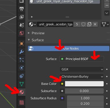
This explains one way of opening an image texture in Blender 2.92. In the right-hand side bar click the pink circular material icon. If 'Surface' is not visible, click the 'Use Nodes' button. In the 'Surface' drop down box select 'Principled BSDF'. Click the small round button next to 'Base Color' (not the main box), select 'Image Texture' from the drop down list. A new bar will open under Base Color, select the 'Open' tab and browse to your image file.
For dae to cas conversion IWTE uses the material name for the texture name to be encoded into the .cas file. The example in the picture 'unit_greek_royal_cavalry_macedon_tga' will be encoded as "textures/unit_greek_royal_cavalry_macedon.tga"
If you need ## prefix to a texture use hh_ and if you need #& prefix use ha_
These translations in the texture name are used to avoid problems in the dae process caused by . # & symbols.
Animated Models
Armature Explanation
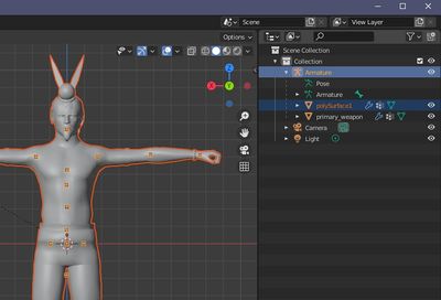
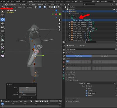
Models which use a bone structure are displayed in Blender with the meshes as 'children' of an Armature. The bones themselves and any pose/anim are also displayed as sections under the main 'Armature' heading, note the indent level in the picture below (in Blender 2.9):
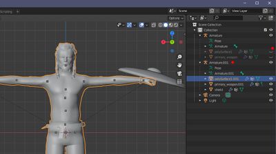
If you import a second model into the same Blender file its mesh will be under a second Armature. In the photo below the visibility of the first model parts has been turned off (hidden) so the second can be seen clearly:
Swapping Parts Between Models
- for discussion/queries see TWC thread here
To swap parts between models import the model with the skeleton bone structure you want to keep first. In some cases the bone structure might be the only thing you want to keep! This is also the method you would use if you wanted to swap the skeleton of a model, e.g. from a normal to slinger variant, or to a custom skeleton.
Import the model with the mesh components you want to use second.
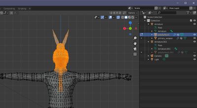
Change and/or delete the parts of each model so that you have only the elements you want to keep. In this example we're getting rid of the head and hair from the first model and replacing with the head and hair from the second.
The body sections have been deleted from the second model leaving only the corresponding head section which is about to be deleted in the picture above. The second model's weapon and shield have also been deleted.
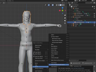
To move the second model's parts into the first Armature first de-parent it select the mesh/es, right click in the main window for menu and select Parent > Clear and Keep Transformation
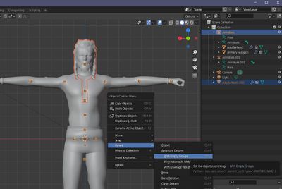
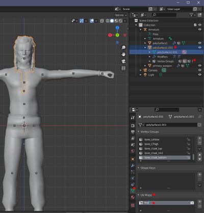
With the mesh/es still selected hold down Ctrl and select the Armature at the top, right click for menu, Parent > With Empty Groups. Other parenting options are possible but the 'with empty groups' one will keep any existing bone weighting IF the bone names in the two armatures are the same. If you had different bone names available in either armature you will need to check that the new parts are correctly weighted at this stage. You should also delete the 2nd now unused Armature. In the picture below you can see that the re-parented mesh still has 'vertex groups', if you don't have that something has gone wrong!
You can now join the meshes together if you need to. Rome Remastered will produce error messages if you have more than 5 polySurface type meshes, you may also want to join the parts so they can be smoothed together. NOTE - if you join meshes with differently named UV Maps in Blender you will lose all but the first UV map! To avoid this change the UV Map name for each mesh in turn before joining, it doesn't matter what the name is so something simple is good:
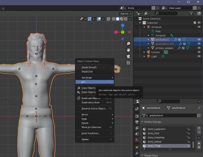
Ideally at this point have a texture visible and applied to the meshes so you can check it doesn't get messed up! You can now join the meshes by selecting them in object mode and 'Join'.
Your model can now be tweaked if necessary, you will want to check that all the parts are correctly mapped for the texture/s they will be using in game.
When exporting the model use the same system you originally imported with, e.g. either fbx and CasConv or dae and IWTE, don't mix and match systems as they all use different scales/orientation!
Bone Assignment
Assigning vertexes to bones is achieved by 'weight painting' in Blender or assigning vertexes to bones in Vertex Groups. If you need to limit the number of bones a vertex is assigned to, e.g. to a single bone for M2TW strat characters or RTW units, you can use 'Limit Total' under the 'Weights' menu, input the number of bones desired in the drop-down mini-menu that appears. To get Vertex Groups applied to new/imported piece of mesh, first make the mesh a child of the Armature parent, using one of the 'Assign from Bones' options. If the automated process didn't get the desired result select the vertex group bone name that you want to assign to, and 'paint' the vertexes.
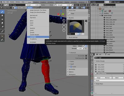
Selecting a bone in the side-bar will make any sections weighted 100% to it show red. Anything not assigned to it will show blue. Areas with a transition partly weighted to it will vary in tone between red>green>blue according to weighting. If you add 1.0 (100%) weighting to two different bones on one vertex it will show as red for both bones until 'Normalized'.
If you are exporting to dae for conversion with IWTE, IWTE will assign any un-assigned vertexes to the first bone in the armature, e.g. the bone_pelvis. It will also limit total weights to two bones per vertex for RR type lod0.cas models and produce a lod1 version with single bone weighting. For other tools e.g. the .fbx CasConv tool you may need to be more precise with your number of bone weights and normalisation.
Select Unassigned Vertexes
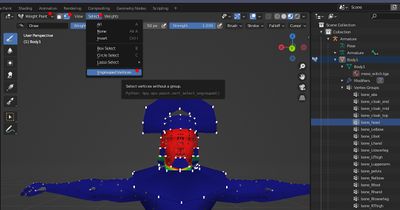
To find and select any completely unweighted vertexes use Weight Paint mode, the vertex selection mode, 'Select > Ungrouped Vertices'.
Weighting in Edit Mode
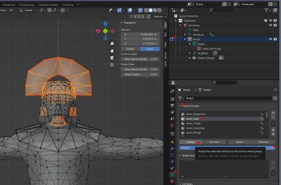
An easy way to assign vertexes to bones for a large area needing 100% weighting is to select the vertexes in Edit mode.
Select the vertexes you want to weight to a particular bone, select the green triangle mesh icon in the side-bar, open the Vertex Groups drop down, select the bone you want to weight to, in the weight bar check the value is what you want, e.g. 1.0 for 100% to the one bone. Click 'Assign'.
Checking an Individual Vertex
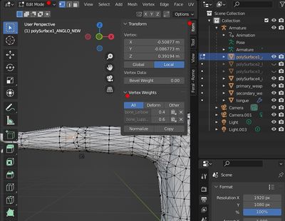
If the colour display in Weight Paint mode does not adequately explain a vertex's weighting you can check it in Edit mode.
Open the mini-side bar (shortcut 'n') and select an individual vertex, in the 'Item' section, if the vertex has bone weighting a 'Vertex Weights' section will be at the bottom showing the ratio of weight to each bone. NOTE: this only works if you select the vertex in selection mode by clicking on it, drawing a selection box around it does not work!
Animations
To start adjusting animations you need to be in "Pose Mode", to view the keyframes in the "Dope Sheet" section and be able to select bones easily, click the pose (running man) symbol in the side-bar, open "Viewport Display" and select "In Front".
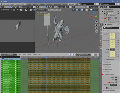
To save a movement to a keyframe, in pose mode with the bones you want to adjust selected, click 'i' in the main window to bring up 'insert keyframe menu' and set the type you want, probably 'location and rotation'.
Bone Constraints
Bones will generally follow the movements of their parent bone/s in the armature, to over-ride this behaviour, or temporarily change the parent relationship you can use "Bone Constraints" on individual bones.
You can impose a constraint only on certain keyframes by manipulating the "Influence" amount. 1.0 will give the constraint full influence and 0.0 will give no influence. To set for an individual keyframe, drag the blue time bar to the desired frame, type the desired number in the influence box then hover over the box and hit the shortcut key "i" to set that value. This can be used if you wish to have a weapon's bone linked to the hand bone for parts of the animation, but set down or stored against the torso for other parts.
Pictured below is an animation in .blend file with bone constraints applied.
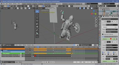
"Shrinkwrap" to a portion of mesh seems to be the only constraint that will make a bone follow acurately an element that isn't its parent in the armature. If you're exporting the animation separately you can temporarily separate a portion of mesh to provide a smaller area to wrap to.
Exporting via Collada will convert the movement paths obtained by the bone constraints to individual keyframe values (as shown in the picture under Animations above), that should then be useable in other programs that may not directly accept the constraint properties.
Fixing Floating Units
If your model mesh and skeleton has been scaled you may need to adjust the bone positions in all the .cas animations relative to ground level to prevent floating units.
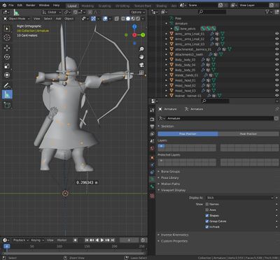
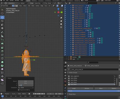
To find out how much you need to adjust the skeleton load your model on it's basepose and at least one animation in Blender. Activate the animation, view in orthognal projection and measure the amount the model needs to be moved by to sit at the required level:
Select the Armature and select 'Edit Mode' for the Armature, select all the bones and move them vertically by the required amount:
Select all the Mesh elements, go to 'Edit Mode' for all of them, select all and move them vertically by the same amount.
Activate the animation again and check that your model now performs the animation at the correct height. If so export the file. You will need to use the basepose information from this file to update the skeleton in ALL of the animations the model uses, and you will need to use the new re-aligned mesh generated from the file too.
For how to use IWTE to update animations see here
Export via Collada to .dae
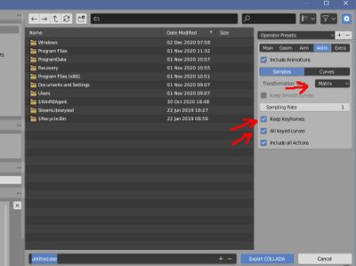
To ensure you save the frames for any bones that might be stationary but in a new pose position select the boxes shown below.
To suit processing by IWTE please use the "Matrix" export option as shown.


